Thursday, 29 May 2014
Final Model Part 2 - 3D Object
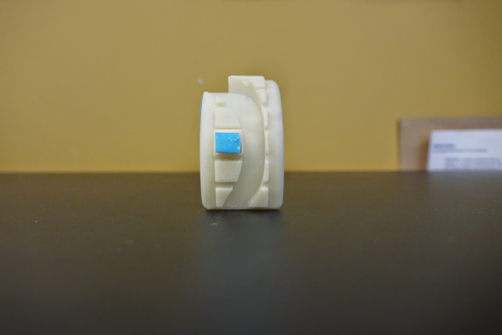
front view - trying to keep all the electronics contained with cable ties and tape.
it fits but also not at the same time - somewhere between the software and printing something must have gone wrong - time and availability didn't allow me to re print and it could have been wrong again - also amount of electronics (wires) is quite large for the minimal space inside the object
Final Model
Here i rendered it on a shade of blue - just to get an idea how it could look like in a different color.
Curve for the vinyl cutter in Adobe Illustrator. The circles are the representation of the speaker.
dimensions for the Illustrator file.
looking inside
from the side.
push here
for the headphone jack.
from the bottom.
Tuesday, 27 May 2014
Models Part 3
this model was the last mock up using the UP printer - because of all the support and scaffolding, the detail inside of the object - like the hooks for the LED's broke off.
the blue vinyl is supposed to show the sound out put but I realised when sticking it on that it would be difficult to stick on the other rings evenly
looking inside - at the scaffolding left inside and the broken hooks
vinyl
with the LED's
LED's
Thursday, 22 May 2014
Further changes
Just some minor changes I made to the model. Every time I had to make adjustments after a completed model, I had to start from the beginning as in Rhino you cant go back to a previous step and once saved I couldn't undo either. Therefore my models had slight variations in the aesthetics part.
I offset the curve for laser cutting, so that it isn't taking anything from the sides away. I indented it 3mm into the model, for the plywood.
to make the path blocks less boxy and more softer I filleted the edges about 1 mm. To do this I had to go back to the beginning where I boolean union the blocks with the curve and fillet the edges before I difference the river path with the object. Otherwise the filleting wouldnt quite work and extends out further.
Also to make it more feminine, I made the height of the path blocks smaller.
LED circuit
Talking to Craig in FabLab about my LED circuit, he showed me this website. Which calculates my resistor from the volts of the LED's and Battery. With this I set up a quick breadboard circuit, to see if it works and then I soldered them all together. I have done them with additional wires so I can position them comfortably into the object. As I have a bit of room in the object I can do this easily.
Since the regular 9V battery doesn't fit into my object anymore, Craig recommended an alkaline 12V battery, which will fit nicely at one of the ends, preferably the end with out the switch.
My circuit consists of 6 blue LED's, 2 resistors, a 12V battery and a momentary switch. A momentary switch is a switch that only lights up the LED's when pushed down. When you release the LED's will turn of again. At the moment the wiring at the switch is a bit loose and the connection to the battery gets loose at times as well.
Monday, 19 May 2014
LED, Headphone Jack, Speaker output and Switch
measurements of the bracelet - bigger dimensions
measurements of the bracelet - smaller dimensions
This part is for the LED to hold in place inside the object. I created it in Autodesk Inventor and then exported it to as a .dwg file to put it back into Rhino and keep transforming it. First I just made a basic rectangle and filleted the top edges. Then I put a 5mm hole into it and filleted the edge as well.
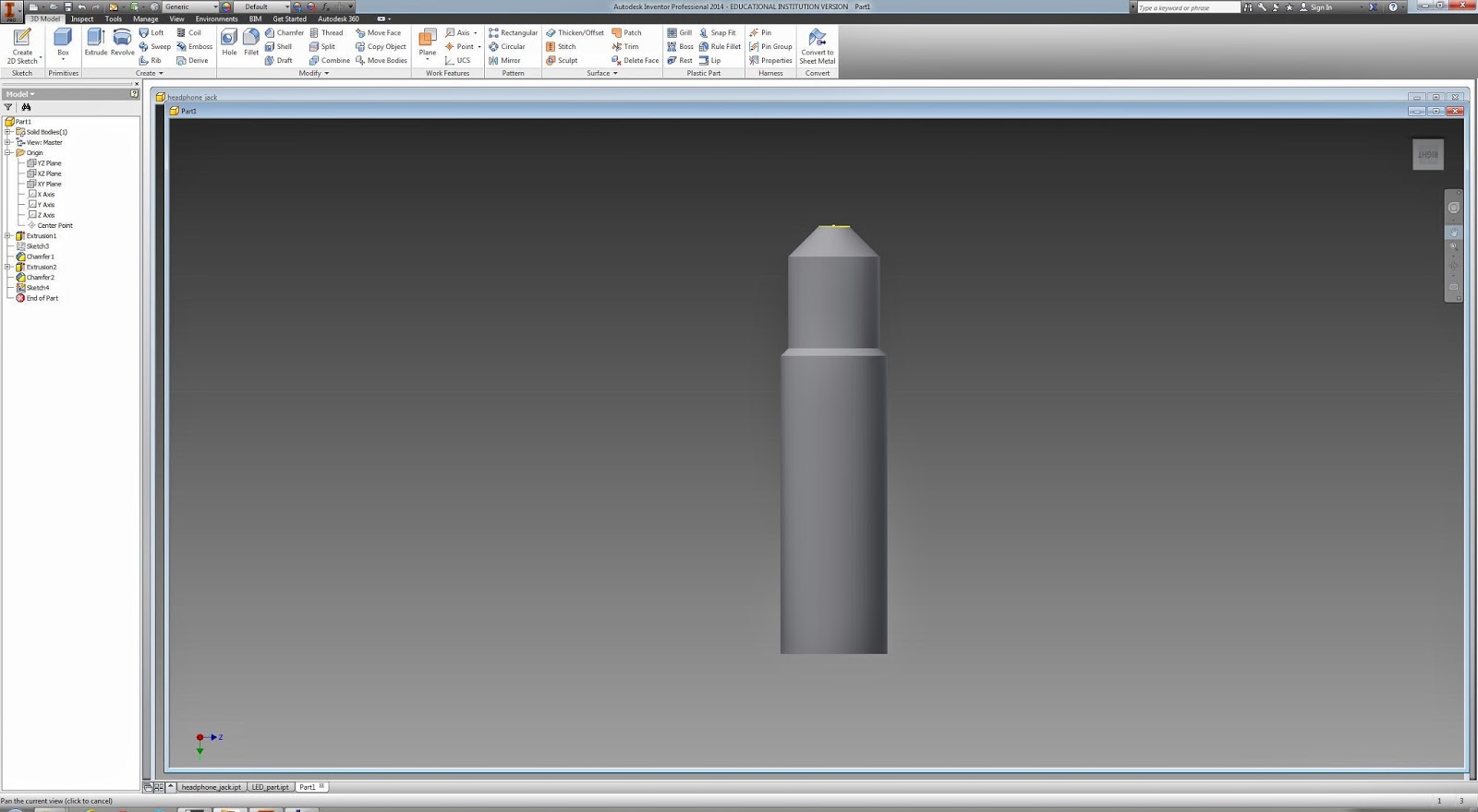
This is a basic headphone jack, I started it in Autodesk Inventor and finished it in Rhino. So I started with basic circles and extrusions to get a basic shape. These then I filleted at the edges and joined them. Inventor is still very unfamiliar to me so in the end couldn't go much further than this. Therefore exported it again as a .dwg file.
Here I imported the file from Inventor and with boolean difference made the grooves.
To make it more visible that the inside bit can be taking out, I added the arrow (triangle) with the two lines underneath which one can see anywhere where a battery is being used, ie. a tv remote.
The 3 shapes I extruded and rotated them to the angle of the curve. Then boolean union one and the other I used boolean difference. The engraved one is most commonly used. I also made the things that hold this all in place in the object, longer as in width and height. Otherwise it would be easier to break off.
The loop for the LED in Rhino. The first thing I did was measure it as last time I used Inventor and the measurements they were always way too big to be printed.
I copied and pasted to make a total of 6. These then rotate to good positions and along the curve. With boolean union I joined them together.
The rectangles at the edges are for the 'lid' so it doesn't fall in as it did before.
Making a cylinder and boolean difference to do the insert for the headphone plug. First I had to Boolean union the cylinder to the object and then do the whole difference thing. It had to be done like this because if I did the boolean difference first and then union it would cut of the end bit of the headphone plug shape.
The switch. The switch is so basic as I just extruded one of the surfaces of the 'path blocks' and sized it down so it floats in there at the moment. Then I'm going to connect it to an actual switch bought from the store jaycar.
front view of all the inside stuff.
Outline shape of the side face with a representation of the speaker output. this will be laser cut either with plywood or acrylic and attached to the side.
Subscribe to:
Comments (Atom)


